

Applets
contents
visual index
 introduction std_logic_1164 gatelevel circuits delay models flipflops adders and arithm... counters LFSR and selftest memories programmable logic state-machine editor misc. demos I/O and displays DCF-77 clock relays (switch-le... CMOS circuits (sw... RTLIB logic RTLIB registers Prima processor D*CORE MicroJava Pic16 cosimulation Mips R3000 cosimu... Intel MCS4 (i4004) image processing ... [Sch04] Codeumsetzer [Sch04] Addierer [Sch04] Flipflops [Sch04] Schaltwerke [Sch04] RALU, Min...
 [Fer05] State-Mac...
 farm-road tr... 2 Floor Elev... 5 Floor Elev... 5 Floor Elev... [Fer05] PIC16F84/... [Fer05] Miscellan... [Fer05] Femtojava FreeTTS
The state-machine in this applet implements the 'elevator-algorithm' to handle all five floors. Once the elevator car has started, it keeps its current direction until all ongoing requests in that direction have been processed. For example, if the elevator is parked at floor1 and someone presses the button on level2 (modeled by state PARKED_1). Naturally, the elevator starts going up to level2 (state UP_TO_2). Now, assume that another person first pressed the button on level0 while the elevator is still moving, and a second person presses the button on level4 shortly afterwards. In this case, the elevator keeps going up to level2, but then continues going upwards to level4, before going down to level0.
However, the state-machine shown here still has a design flaw, because the elevator doesn't pause at intermediate floors when people are waiting at the corresponding level. Implementing the correct behaviour including the pauses makes for a nice design-challenge. Technically, note that the state-machine is clocked at 1 KHz clock rate, so that the (short) pulses from the floor sensors are detected reliably. Adding meaningful pauses of a few seconds would require thousands of extra states, or an external wait counter, or a redesign of the animated elevator simulation component so that a slower clock rate could be used.
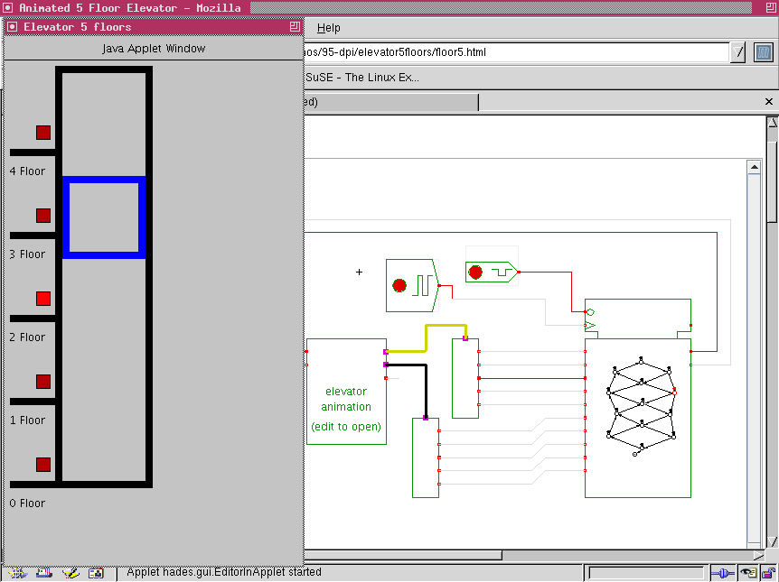
Use the popup-menu ('edit') on the elevator component to open the window with the elevator visualization. Press any floor button and watch the behavior of the elevator controller. You can also open the state-machine editor to watch and edit the controller. The following image shows a screenshot of the applet with both the elevator animation and the state-machine editor open at the same time:
 Elevator has five buttons, one on each floor.
In addition, there are floor level sensors. When the
elevator is on the ground floor, the ground sensor is ON. If the
elevator moves up, the ground sensor is OFF, and the K level sensor
will be switched ON when the elevator arrives on the K floor.
The engine and direction are elevator inputs.
Inputs:
engine: ON and OFF
direction: move up (ON), move down (OFF)
Outputs:
Sensor: 5-bit vector, where the bit K will be ONE if the elevator is on K floor, otherwise OFF
Button: 5-bit vector, Switch the bitk ON if pressed, and stay ON until the elevator arrives at K floor.
Component written by André Bigonha, Ulisses Chippe, Giliardo Freitas and
Ricardo Ferreira, DPI, Universidade Federal Vicosa, Brazil, cacau@dpi.ufv.br
To edit the state-machine, activate the popup-menu on the
FSM symbol and select the edit menu item.
This opens the editor window for the FSM,
which uses a mode-oriented user-interface.
Hint:
Please be cautious when using the 'check FSM' method in the FSM editor.
As the elevator controller has 10 inputs, the check FSM function might
report up to 1024 errors (210) for every state in your machine,
which can take a long time and a lot of memory.
Elevator has five buttons, one on each floor.
In addition, there are floor level sensors. When the
elevator is on the ground floor, the ground sensor is ON. If the
elevator moves up, the ground sensor is OFF, and the K level sensor
will be switched ON when the elevator arrives on the K floor.
The engine and direction are elevator inputs.
Inputs:
engine: ON and OFF
direction: move up (ON), move down (OFF)
Outputs:
Sensor: 5-bit vector, where the bit K will be ONE if the elevator is on K floor, otherwise OFF
Button: 5-bit vector, Switch the bitk ON if pressed, and stay ON until the elevator arrives at K floor.
Component written by André Bigonha, Ulisses Chippe, Giliardo Freitas and
Ricardo Ferreira, DPI, Universidade Federal Vicosa, Brazil, cacau@dpi.ufv.br
To edit the state-machine, activate the popup-menu on the
FSM symbol and select the edit menu item.
This opens the editor window for the FSM,
which uses a mode-oriented user-interface.
Hint:
Please be cautious when using the 'check FSM' method in the FSM editor.
As the elevator controller has 10 inputs, the check FSM function might
report up to 1024 errors (210) for every state in your machine,
which can take a long time and a lot of memory.
- move-mode: Click-and-drag any one of the state symbols (circles) to a new location on the editor canvas. The currently selected state is highlighted in red. Use the textfield on the lower left to set the name of the selected state. To change the output values for Moore-type outputs in the selected state, first select that output in the list on the lower left and then select the new output-value (0 or 1) in the radio-button on the bottom.
- state-mode: Click the mouse to create a new state and set its name and the default output values via the GUI controls on the lower left part of the editor window.
- transition-mode: To create a new transition between states, first click of the initial state, then on the final state. Enter the logical condition that activates the transition in the textfield on the lower left, e.g. "*" for an always active transition, or "A&B" for a transition that is only active if the "A" and "B" inputs are both active (1).
- comment-mode: Click the mouse to specify the position for a new text comment on the editor canvas; next enter the comment into the text-area in the lower left part of the editor window and finally press "apply" to create the comment.
- delete-mode: Click the mouse to delete a state, transition, or comment.
- starting state-mode: Click the mouse on a state symbol to select that state as the initial starting-state of the FSM.
- Click the test FSM button to run a simple selftest that checks for each state whether transitions are active for any combination of inputs.
- Use the load and save as operations to load or save the FSM design file.