| Detectors and counters demonstration
Circuit Description
This applet demonstrates the detector and counter
simulation components.
Naturally, the detectors can be combined with other simulation models
and user-defined logic.
On the top, a simple value detector
(hades.models.special.ValueTrigger) is used.
This simulation model generates a short (1 nanosecond) 0-1-0 pulse
on its Q output whenever the previously selected input value is detected.
Any of the nine logical values of the std_logic_1164 system can be
used as the sensitive value for the detector, e.g. to pause the simulation
as soon as the input signal changes to a "U" or "X" unknown value.
In the applet, the trigger is made sensitive to the "H" (weak high) value,
while the SR-flipflop is set by an 0-1-0 pulse generated by the trigger.
Just use the input switch to generate the different std_logic input values
and observe the behaviour of the trigger. Use the reset switch to reset
the SR-flipflop after it has been set by a "H" value on the trigger input.
Below the first group of components, an edge detector
(hades.models.special.EdgeTrigger) shows how to detect arbitrary edges.
In the applet, the detector generates a short (1 nanosecond) 0-1-0 pulse
for every 0-1 edge on its input (that is, a standard rising edge of the
input signal).
The logical values for the before- and after-states of the edge
can be selected from the drop-down menus in the edge detector's
property sheet.
Again, a SR-flipflop is set by the detectors output to store the
trigger condition.
The bottom group of components demonstrates both the universal
counter (hades.models.special.Counter) and the
hazard detector (hades.models.special.HazardTrigger).
The counter component is used to count either events, values,
or rising and falling edges on its input signal.
Internally, the counter always stores and updates all of its values,
but only one value is shown on its symbol or its property sheet.
Click onto the square in the counter's symbol to toggle through
the different counter values, or select them directly from the
drop-down menu it the property sheet.
Clicking onto the circle will clear all internal counter values.
In the applet, the first counter is configured to count and show all
simulation events on the clock signal, while the second counter shows
all 1-values on the clock signal.
As the clock signal changes between the 0- and 1-values, there are
twice as many clock events as 1-values.
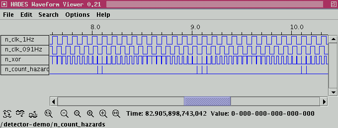
The remaining components use the XOR of two clock signals with
slightly different period (1.00 Hz and 0.91 HZ) to demonstrate
interference and hazards.
Due to the differing periods, the clock signals change their values
at different times, sometimes resulting in short pulses at the
XOR gate output.
The hazards-detector is set to generate a 0-1-0 pulse whenever
the input signal has a value of 1 for less than 0.05 seconds duration.
Both the sensitive value (or edge) and the required duration can
be specified via the property sheet.
The counter is then used to count the number of detected hazards.
The following screenshot image shows the waveforms of both clock signals
(1.00 Hz and 0.91 Hz), the XOR of the clock signals,
and the output of the hazard detector when set to react to
1-hazards of less than 0.05 seconds duration:

| | |


 introduction
 std_logic_1164
 std_logic va...
 std_logic lo...
 switches
 basic gates
 hex-switch
 clock generator
 two-phase clock
 resolution f...
 wired-AND demo
 detectors an...
 gatelevel circuits
 delay models
 flipflops
 adders and arithm...
 counters
 LFSR and selftest
 memories
 programmable logic
 state-machine editor
 misc. demos
 I/O and displays
 DCF-77 clock
 relays (switch-le...
 CMOS circuits (sw...
 RTLIB logic
 RTLIB registers
 Prima processor
 D*CORE
 MicroJava
 Pic16 cosimulation
 Mips R3000 cosimu...
 Intel MCS4 (i4004)
 image processing ...
 [Sch04] Codeumsetzer
 [Sch04] Addierer
 [Sch04] Flipflops
 [Sch04] Schaltwerke
 [Sch04] RALU, Min...
 [Fer05] State-Mac...
 [Fer05] PIC16F84/...
 [Fer05] Miscellan...
 [Fer05] Femtojava
 FreeTTS