TAMS / Java / Hades / applets (print version): contents | previous | nextinput and output components
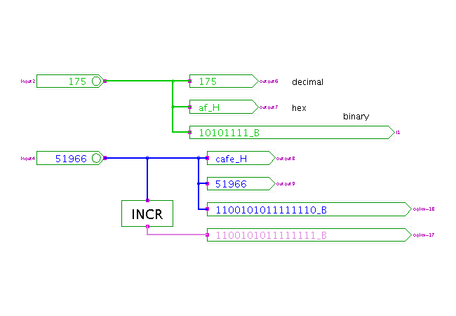
 DescriptionThis is the first applet in our applet-collection
based on the RTLIB set of simulation components
for register-transfer-level demonstrations.
The applet shows the interactive switch (called IpinVector),
the corresponding output connector with display (called OpinVector),
and an incrementer.
StdLogicVector and SignalStdLogicVector:
The RTLIB library is based on the same concept of multi-bit signals
and operators as the VHDL std_logic_vector datatype.
The current implementation relies on two main Java classes.
While StdLogicVector (class hades.models.StdLogicVector)
provides the basic data-type and most logical and arithmetic operations,
SignalStdLogicVector (class hades.signals.SignalStdLogicVector)
provides the corresponding signal type.
Unlike the VHDL std_logic_vector data type,
the current implementation of class StdLogicVector
is limited to signals with up to 63 bits.
(We use a very efficient internal representation based on long integers,
which keeps the implementation simple and guarantees acceptable performance.
Also, buses wider than 64 bits are seldom required for demonstrations.
If necessary, the class could be rewritten to support wider buses.)
The hades.models.rtlib package and its sub-packages hold the
simulation components that operate on SignalStdLogicVector.
The IpinVector component is used as the interactive switch
to generate inputs values,
while OpinVector is used to display the current signal
values.
Both IpinVector and OpinVector also act as hierarchy connectors
that define the inputs and outputs of subdesigns in a design hierarchy.
Glow-mode:
If glow-mode is selected in the editor, the color of bit-vector signals
is based on their current numerical value.
The last digit of the decimal representation (i.e. value modulo 10)
is used as an index to a table of ten different colors:
0=black, 1=brown, 2=red, 3=orange, 4=yellow, 5=green,
6=blue, 7=lilac, 8=gray, 9=dark blue-green.
(Incidentally, these color are similar to the colors used to
encode the values of resistors).
The standard cyan, magenta, and orange colors are used for
un-initialized (at least one 'U' bit), undefined (at least one 'X' bit),
or tri-stated (all 'Z' bits) signals.
IpinVector usage:
- click an IpinVector to increment its current value
- shift+click an IpinVector to decrement its current value
- control+click an IpinVector to generate the special values
ZZZ (all bits tristated), XXX (all bits undefined),
and UUU (all bits un-initialized).
Both the incrementing and decrementing will wrap-around at the
largest number supported by the selected bit-width.
The upper signal in the applet uses 8-bits, so that values wrap
around at 255, while the lower signal uses 16-bits and wraps around
at 65535.
Note that a normal click in one of the ZZZ, XXX, or UUU states
will reset the output value to 0, while a shift+click will
reset the output value to the highest possible value.
Open the IpinVector property-sheet dialog window to directly
enter a value numerically.
The parser understands decimal numbers as well as hexadecimal numbers
(written as cafe_H or 0xcafe)
and binary values (written as 00101100_b).
Enter the value and press the 'apply' or 'ok' buttons to
change the current output value of the IpinVector component.
You can also change the default number formatting (decimal, hex, binary)
via the IpinVector property-sheet.
In this applet, the upper IpinVector uses decimal formatting,
and the lower is set to hex formatting.
Clicking on an OpinVector will toggle its number formatting
through the (decimal, hex, binary) states.
For larger bit-widths, the default size of OpinVector is too small
to fully contain the binary values (which results in redraw problems).
The variant classes IpinVectorLarge and OpinVectorLarge
(used three times in this applet)
behave exactly like IpinVector and OpinVector,
but use wider symbols that are better suited for the binary representation.
Run the applet | Run the editor (via Webstart)
Impressum | 24.11.06
http://tams.informatik.uni-hamburg.de/applets/hades/webdemos/50-rtlib/00-intro/ipinvector_print.html


 DescriptionThis is the first applet in our applet-collection
based on the RTLIB set of simulation components
for register-transfer-level demonstrations.
The applet shows the interactive switch (called IpinVector),
the corresponding output connector with display (called OpinVector),
and an incrementer.