TAMS / Java / Hades / applets (print version): contents | previous | nextJK-flipflop
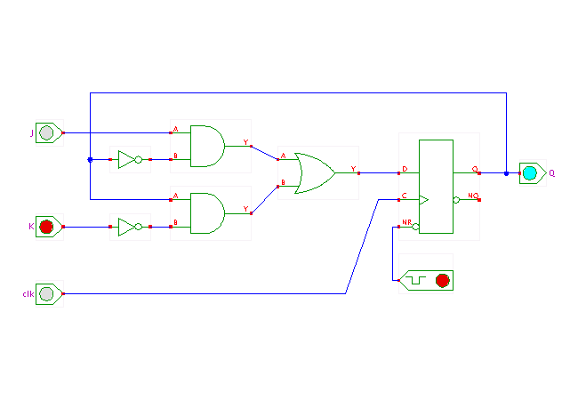 DescriptionThis circuit shows the basic archictecture of the so-called
JK-flipflop,
which consists of a few logic gates in front of a D-flipflop.
On the rising edge of the clock, the flipflop enters a new state
depending on the input values on the J and K inputs:
DescriptionThis circuit shows the basic archictecture of the so-called
JK-flipflop,
which consists of a few logic gates in front of a D-flipflop.
On the rising edge of the clock, the flipflop enters a new state
depending on the input values on the J and K inputs:
- J=0, K=0: store (Q=Q)
- J=0, K=1: clear (Q=0)
- J=1, K=0: set (Q=1)
- J=1, K=1: toggle (Q=!Q)
While JK-flipflops are not often used in modern integrated circuits,
they were very popular during the TTL era of circuit design
because of their flexibility.
A JK flipflop can emulate most other types of flipflops
including D-flipflops and T-flipflops
with suitable wiring of the J and K inputs
(a few additional gates in front of the J and K inputs might be required).
To ease the construction of counters,
JK-flipflops are often sensitive to the falling-edge of the clock signal.
The actual implementation of a JK-flipflop in TTL-technology
does not rely on the circuit shown here,
but uses a master-slave flipflop structure demonstrated in the
next applet.
Run the applet | Run the editor (via Webstart)
Impressum | 24.11.06
http://tams.informatik.uni-hamburg.de/applets/hades/webdemos/16-flipflops/40-jkff/jkff-prinzip_print.html