|
EMC TEST REPORT
No. E74902.I
Immunity to electromagnetic disturbances
EQUIPMENT UNDER TEST
Equipment: Noise generator module for computers
Type/model: SG 100
Manufacturer: Protego Information AB
Tested by request of: Protego Information AB
SUMMARY
Referring to the performance criteria and the operating mode during
the tests specified in this report the equipment complies with the
requirements according to the following standard.
EN 50082-2: 1995
Date of issue: December 19, 1997
Tested by: Stefan Hagdahl

Page
1. CLIENT INFORMATION.............................................3
2. EQUIPMENT UNDER TEST (EUT).....................................3
2.1 Identification of the EUT...................................3
2.2 Additional information about the EUT........................3
2.3 Peripheral equipment........................................3
3. TEST SPECIFICATIONS............................................4
3.1 Standards...................................................4
3.2 Additions, deviations and exclusions from standards.........4
3.3 Purpose of the test.........................................4
3.4 Mode of operation during the test...........................4
3.5 Performance criteria........................................4
3.6 Performance verification....................................4
4. TEST SUMMARY...................................................5
5. IMMUNITY TO ELECTROSTATIC DISCHARGE, EN 61000-4-2(1995)........6
5.1 Operating environment.......................................6
5.2 Test set-up.................................................6
5.3 Test conditions.............................................6
5.4 Measurement uncertainty.....................................7
5.5 Test equipment..............................................7
5.6 Test protocol...............................................7
6. IMMUNITY TO RADIATED ELECTROMAGNETIC FIELDS, ENV 50140(1993)...8
6.1 Operating environment.......................................8
6.2 Test set-up.................................................8
6.3 Generation of electromagnetic field.........................9
6.4 Test conditions.............................................9
6.5 Measurement uncertainty.....................................9
6.6 Test equipment..............................................9
6.7 Test protocol..............................................10
7. IMUNITY TO POWER FREQUENCY MAGNETIC FIELD, EN 61000-4-8(1993).11
7.1 Operating environment......................................11
7.2 Test set-up................................................11
7.3 Test conditions............................................11
7.4 Test instrumentation.......................................11
7.5 Test Protocol..............................................11
Test report no. E74902.I
Page 3 (12)
1. CLIENT INFORMATION
The EUT has been tested by request of:
Company: Protego Information
Citadellsvägen 11
211 18 Malmö
Name of contact: Bo Dömstedt
Telephone: 040-94 05 00
Telefax: 040-30 36 46
2. EQUIPMENT UNDER TEST (EUT)
2.1 Identification of the EUT
Equipment: Noise generator module for computers
Type/model: SG 100
Manufacturer: Protego Information AB
Citadellsvägen 11
2ll 18 Malmö
Country of origin: Sweden
Rating: DC via computer connector
2.2 Additional information about
the EUT
Internal clock frequencies or other frequencies used: 100 kHz
2.3 Peripheral equipment
Defined as equipment needed for correct operation of the EUT, but not
considered under test.
System: computer Compaq
System: optolink Fiberdata:RS 232/-C MIL
System: Battery box
3. TEST SPECIFICATIONS
3.1 Standards
EN 50082-2, (1995): Generic immunity standard.
Part2. Industrial environment
Basic standards:
EN 61000-4-2 (1995): Electrostatic discharge requirements.
Required test level: Contact discharge 4 kV, air discharge 8 kV.
ENV 50140 (1993): Radiated electromagnetic field requirements.
Required test level: 3/10 V/m, AM 80% (1kHz), 80-1000 MHz
EN 61000-4-4 (1995): Electrical fast transient/burst requirements.
Required test level: 1.0 kV AC supply,
0.5 kV DC supply and signal/control lines.
ENV 50141 (1993): Conducted disturbances.
Required test level: 10 V on AC supply,
1 V DC supply and signal/control lines
AM 80% (1kHz)
EN 61000-4-8 (1993): Power frequency magnetic field immunity test.
Required test level: 30 A/m
3.2 Additions, deviations and
exclusions from standard
No additions, deviations or exclusions have been made from standard
3.3 Purpose of the test
Purpose of the test: To determine whether the equipment under test
fulfils the EMC-immunity requirements stated in section 3.1 and 3.5
3.4 Mode of operation during
the test
EN 61000-4-2: The EUT was connected directly to the computer.
ENV 50140: The EUT was connected to the computer via a batterymodule and
a optolink cable.
EN 61000-4-8: The EUT was connected to the computer via a batterymodule
and a optolink cable.
3.5 Performance criteria
The Performance criteria are based on the general criteria in the
standard and specified by the manufacturer.
Criterion
A: The EUT shall continue to operate as intended during
the test without disturbances
of the function.
Significant changes of the computer test sequence
were not allowed.
Criterion B: The EUT shall continue to operate as intended without
disturbances of the function after the interference is
removed. Changes the computer test sequence were were
not allowed to remain after the completion of the test.
3.6 Performance verification
EN 61000-4-2 The computer was monitored directly by the test engineer.
ENV 50140 and EN 61000-4-8: The computer was monitored directly by the
client representative observer (software manufacturer)
4. TEST SUMMARY
The results in this report apply only to sample tested:
| Test |
Passed the
test |
Note |
| EN 61000-4-2: Electrostatic
discharge |
Yes |
|
| ENV 50140(1993): Radiated
electromagneticfields |
Yes |
|
| EN 61000-4-4: Electrical
fast transients |
- |
Not Applicable |
| ENV 50141: Conducted immunity
requirements |
- |
Not Applicable |
| EN61000-4-8(1993): Power
frequency magnetic field |
Yes |
|
EN 61000-4-2: The EUT was tested up to 4 kV with contact discharge and
up 8 kV with air discharge.
No function disturbances was observed after the interference was removed.
The EUT fulfilled the performance criterion B.
ENV 50140: The EUT was tested at 10 V/m with two sides facing the antenna.
No interference was observed during the test.
The EUT fulfilled the performance criterion A.
En 61000-4-8(1993): The EUT was tested 30 A/m (50 Hz).
No interference was observed during the test.
The EUT fulfilled the performance criterion A.
5. IMMUNITY TO ELECTROSTATIC
DISCHARGE, EN 61000-4-2 (1995)
5.1 Operating environment
Temperature: 19°C (15-35°C)
Relative Humidity: 41 % (30-60 %)
5.2 Test set-up
The EUT was placed on a non-metallic support 0,1 m above a reference
ground plane (RGP) and was operated according to the specified operating
mode.
A vertical couplingplane (VCP) was connected to the RGP with a cable with
two 470 kohm resistors.

5.3 Test conditions
Test level: 4 kV Contact discharge
8 kV Air discharge
Number of discharges
at each point: 10 of each polarity
Performance criterion: B
EUT position: Floor standing
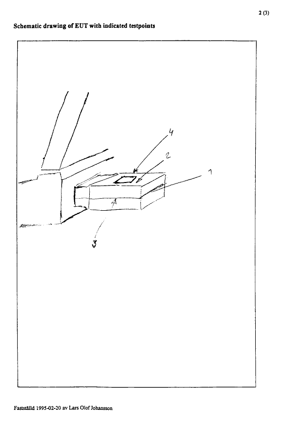
The selected test points of the EUT are listed in this table, the numbers
refer to the drawing below.
| Point |
Description |
| VCP |
0.1 m from the back and
right side of the EUT |
| 1 |
back of the EUT |
| 2 |
top of the EUT |
| 3 |
right side of the EUT |
| 4 |
left side of the EUT |
Indirect contact discharges were
applied to the VCP.
5.4 Measurement uncertainty
The uncertainty of the applied alectrostatic discharges are within the
tolerance specified by the standard.
5.5 Test equipment
Equipment MAnufacturer and type Serial no.
ESD-generator: EM TEST, ESD 30 1095-85
Reference ground plane: 1.6 x 0.8 m.
Vertical coupling plane: Aluminium: 0.5m x 0.5m + 1.5mm
5.6 Test protocol
Date of test: December 16, 1997
| Test point # |
Test level (kV) |
Air/Contact |
Polarity (+/-) |
Pass/Fail |
Comment |
| 1 |
8 |
Air |
+/- |
Pass |
discharges,
but no disturbances |
| 2 |
8 |
Air |
+/- |
Pass |
discharges,
but no disturbances |
| 3 |
8 |
Air |
+/- |
Pass |
discharges,
but no disturbances |
| 4 |
8 |
Air |
+/- |
Pass |
discharges,
but no disturbances |
| VCP |
4 |
VCP Contact |
+/- |
Pass |
discharges,
but no disturbances |
6 IMMUNITY TO RADIATED ELECTROMAGNETIC
FIELDS, ENV 50140(1993)
6.1 Operating environment
The test was performed in a semi-anechoic shielded chamber.
Temperature: 19°C
Relative humidity: 41 %
6.2 Test set-up
The EUT was placed on a non metallic table 0.8 m above the reference
grounde plane (RGP) and was operated in the operating mode specified.
Photos of the test set-up are included in appendix I.
Absorbers were placed on the RGP between the EUT (0.3m in front of the
EUT)
and the antenna to reduce the reflections from the RGP.

SG100 connected to battery box. The grey optical fibre cable
from the battery box connects the SG100 to a monitoring computer.
Yellow object to the right of the picture measures the strength of
the applied electromagnetic field.

6.3 Generation of the electromagnetic
field
The electromagnetic field is generated from a computer controlled signal
generator. The output power is amplified and the radiated from a broad
band ni log periodic antenna.
A field probe was placed 1 m to the right of the EUT, and at each frequency
the power to the antenna was adjusted until the probe reading showed the
wanted field strength.
6.4 Test conditions
Test level: 10 V/m
Performance criterion: A
Frequency step: 1 %
Dwell time at each frequency: 3 s
Field orientation: Horizontal and vertical
Antenna distance: 3.0 m
Exposed sides: Front and rear
6.5 Measurement uncertainty
The measurement uncertainty is ±2.0 dB.
Measurement uncetainty is calculated in accordance with WECC 19-1990.
The measurement uncertainty is given with a confidence of 95 %.
The measurement uncertainty is calculated as the uncertainty of the
electric field intensity detected by the probe.
The Uncertainty calculations exclude influence of phenomena like
inhomogenity of the electric field intensity.
6.6 Test equipment
Equipment Manufacturer and type Serial No.
Computer: JKS, Pentium 100 Mhz
Software: Chase CIS 9942 Ver 3.02
Field probe: Chase EMC 20 field probe F-0028
Signal generator: Rhode &Schwarz, SMY01 84234/014
Amplifier;
27 MHz-1000 MHz GTC GRF5041 1813
RF Power Meter: Rhode &Schwarz, NRVD 839111/036
Power head: Rhode &Schwarz, URV5-Z4 841.498/042
Rhode &Schwarz, URV5-Z2 841819/011
Directional coupler: Werlaton C2630 4496
X-wing bilog
transmitting antenna
20-2000 MHz: Chase CBL6140 1027
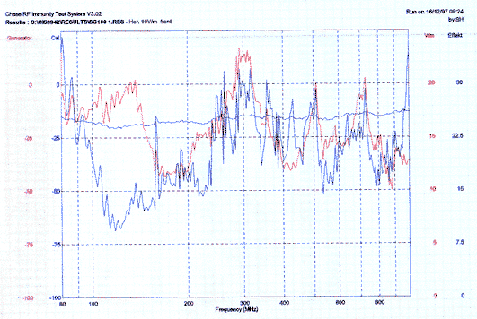
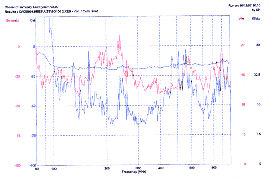
Graph of applied
signal power and the resulting
electromagnetic field
Horisontal field

Vertical field

As
the SG100 is a security device we would like to see what happens when
the applied field becomes stronger. When the two tests above was completed
an attempt was made to adjust the RF-signal as to influence the SG100
generator.
After some experiments it was clear that the SG100 would not fail to
operate if a stronger field was applied.
We then opened the semi-anechoic shielded chamber and moved the transmitter
antenna closer to the SG100 generator (this is a non-standard modification
of the test set-up).
The shielding (the casing) of the SG100 was removed from the test device.
The maximum permittable output power was enabled from the amplifier.
Some experiments then took place, including the use of a signal in short
bursts, but still no faults in the output could be detected.
A sweep from 80MHz-1000MHz was run, with maximum power (200W), and with
no casing mounted on the SG100.
Graph of sweep with maximum
power applied

It is evident, from this extra test, that
A) To detect a device failure, a stronger field than 40 V/m must be
applied.
B) The SG100 electric circuit may with a high probability work well
even
if subject to strong electromagnetic fields (such as the "heavy
industry"
requirements of 30 V/m).
C) Note that if the random number production stops, this will be detected
by the SG100 software driver. It is unclear what type of signal, and
of what strength, that will be needed in order to be able to influence
the
output from the software driver.
D) It was not possible to measure how well the SG100 circuit is protected
by
the shielding casing. Other types of casing under consideration was
also
available at the test site, as the intention was to evaluate different
types of casing.
6.7 Test protocol
Date of test: December 16, 1997
Client representative observer: Bo Dömstedt
Test
no. |
Freq.
(MHz) |
Level
(V/m) |
Pol.
V/H |
Operating mode/
Exposed side |
Pass/
Fail |
Comment |
| 1 |
80-1000 |
10 |
V |
Front |
Pass |
|
| 2 |
80-1000 |
10 |
H |
Front |
Pass |
|
| 3 |
80-1000 |
10 |
H |
Back |
Pass |
|
| 4 |
80-1000 |
10 |
V |
Back |
Pass |
|
7. IMMUNITY TO POWER FREQUENCY MAGNETIC FIELD, EN 61000-4-8, (1993)
7.1 Operating environment
Temperature: 21 C (15-35 C)
Relative Humidity: 41 % (25-75 %)
7.2 Test set-up
The EUT was placed in the centre of a conducting coil which was 30 cm
in diameter. The EUT was operated according to the specified operating
mode and was tested when oriented in X, Y and Z with reference to the
magnetic field.
7.3 Test conditions
Test level: 30 A/m
Performance criterion: B
Duration of each test: 2 min
Frequency: 50 Hz
7.4 Test instrumentation
Equipment Manufacturer and type Serial No.
Induction coil: n=250t, =0.75 mm2, fi=30cm Emp-001
Magnetic field detector: EMDEX C-520
Power transformer: Combinova 330 AC Source
7.5 Test protocol
Date of test: December 16, 1997
Client representative observer: Bo Dömstedt
| Test No. |
Position of the EUT |
Pass/Fail |
Comment |
| 1 |
X |
Pass |
|
| 2 |
Y |
Pass |
|
| 3 |
Z |
Pass |
|
An additional test was
performed where the coil was loaded with
the maximum allowed current.
No disturbance of any kind was observed.

|


