|
MC-Lab Page 1(7)
EMC TEST REPORT
No. E74902.E
Emission of electromagnetic disturbances
EQUIPMENT UNDER TEST
Equipment : Noise generator module for computers
Type / model : SG 100
Manufacturer : Protego lnformation AB
Tested by request of : Protego lnformation AB
SUMMARY
The equipment complies with the requirements according to the following
standard,
Generic standard EN 50 081-1 (1997)
Date of issue: December 19, 1997
Tested by:
Stefan Hagdahl
Test report no. E74902.E
Page 2 (7)
CONTENTS
Page
1. CLIENT INFORMATION..................................3
2. EQUIPMENT UNDER TEST (EUT)..........................3
2.1 Identification of the EUT.........................3
2.2 Additional information about the EUT..............3
2.3 Peripheral equipment..............................3
3. TEST SPECIFICATION..................................4
3.1 Standards.........................................4
3.2 Aditions, deviations and exclusions from standard.4
3.3 Purpose of the test...............................4
3.4 Mode of operation during the test.................4
4. TEST SUMMARY........................................4
5. RADIATED ELECTROMAGNETIC FIELD......................5
5.1 Operating environment.............................5
5.2 Test set-up and test procedure....................5
5.3 Measurement uncertainty...........................5
5.4 Test Instrumentation..............................6
5.5 Test protocol.....................................6
Test report no. E74902.E
Page 3 (7)
1. CLIENT INFORMATION
The EUT has been tested by request of:
Company: Protego Information AB
Citadellsvägen 11
2ll 18 Malmö
Name of contact: Bo Dömstedt
Telephone: 040-94 05 00
Telefax: 040-30 36 46
2. EQUIPMENT UNDER
TEST (EUT)
2.1 Identification of the EUT
Equipment: Noise generator module for computers
Type/model: SG 100
Manufacturer: Protego Information AB
Citadellsvägen 11
2ll 18 Malmö
Country of origin: Sweden
Rating: DC via computer connector
2.2 Additional information about the EUT
Internal clock frequencies or other frequencies used: 100 kHz
2.3 Peripheral equipment
Defined as equipment needed for correct operation of the EUT, but not
considered under test.
System : Battery box
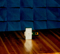
The SG100 was first
connected to a compter to make sure that
it was running. The cable between the computer and the SG100 was then
disconnected, leaving the SG100 running on battery power from the box.
When the cable has been disconnected, the wood table may be rotated
using
remote controls.
picture of test set-up
As no emissions at all was detected, a discussion took place
in the control room, if the radio-receiver was really switched on or
not. The correct operation of the test system was checked by inserting
a small radio transmitter inside the room.
Graph of emmission output
The maximum alowed emission of 40 dBµV (0-200 MHz)
and 47 dBµV (200-1000MHz) has been marked with a red line
Figures
Test report no, E74902.E
Page 4 (7)
3. TEST SPECIFICATIONS
EN 50 081-1 (1992): Generic emission standard, Part l : Residential,
commercial and light industry.
Basic standards:
EN 55 022 (1994) + Amendment l (1995): Limits and methods for
measurement of radio disturbance characteristics of information technology
equipment (ITE).
Class B.
3.2 Additions, deviations and exclusions from standard.
No additions, deviations or exclusions have been made from standard,
3.3 Purpose of the test
Purpose of test: To determine whether the equipment under test fulfils
the EMC-emission requirements of the standards stated in section 3.1
3.4 Mode of operation during the test
The EUT was connected to a battery box,
4 TEST SUMMARY
The results in this report apply only to sample tested:
|
Passed the test
|
Note
|
Mains terminal continuous disturbance voltage
|
-
|
Not Applicable
due to DC supply
|
Radiated electromagnetic field
|
Yes
|
|
Mains terminal discontinuous disturbance voltage
|
-
|
Not Applicable
due to DC supply
|
Test report no. E74902.E
Page 5(7)
5. RADIATED ELECTROMAGNETIC FIELD
IN THE FREQUENCY RANGE 30 MHz TO 1000 MHz
5.1 Operating environment
Measurements were performed in a semi-anechoic chamber.
EUT housing:
Temperature: 19°C
Relative Humidity: 4l %
Measurement receiver:
Temperature: 20°C
Relative Humidity: 4l %
5.2 Test set-up and test procedure
The EUT was positioned in order to obtain maximum disturbance.
An overview sweep with peak detection of the electric field intensity
was performed in a semi-anechoic chamber.
The overview sweep was performed with the antenna set to 1.7 m
in both horizontal and vertical polarisation.
Measurement was repeated with the EUT rotated in 45 degree steps.
The radiated disturbance electric field intensity was measured in a
semi-anechoic chamber, at a distance of 3 m.
The EUT was placed on a non-metallic turntable, 0.8 m above the
RGP.
The table was rotated a full revolution in order to obtain maximum
values of the electric field intensity,
The measurement was made in both the vertical and horizontal
polarisation and the maximum value is presented in the report.
Measurements were performed with a quasi-peak detector.
Due to low emission level (well under the limit line) no OATS -open area
test site measurements were performed.
5.3 Measurement uncertainty
Radiated disturbance electric field intensity, 30-200 MHz: ±3,0 dB
Radiated disturbance electric field intensity, 200-1000 MHz: ±2,5 dB
The measurement uncertainty describes the overall uncertainty of the
given measured value during operation of the EUT in the above mentioned
way.
Measurement uncertainty is calculated in accordance with WECC 19-1990.
The measurement uncertainty is given with a confidence of 95%:
Test report no. E74902.E
Page 6 (7)
5.4 Test instrumentation
Equipment
|
Manu.
|
Type
|
Serial no.
|
Test site:
|
Semi-anechoic shielded chamber.
5 x 8 x 4 m ( W x L x H ).
|
Computer
|
JKS
|
Pentium 100 Mhz
|
|
Software
|
R&S
|
ESPC-K1
|
2.03
|
Measurement receiver
|
R&S
|
ESPC
|
842888/011
|
Spectrum analyser
|
Adv.
|
R3361A
|
11730343
|
Amplifier
|
HP
|
8447F
|
3113A0647
|
Antenna
|
Chase
|
CBL6140
|
1027
|
HP = Hewlett-packard, R&S = Rohde & Schwarz, Adv. = Advantest
5.5 Test protocol
Date of test: December 16, 1997
Antenna pos: Vertical
|
|
|
Disturbance level
/dB(µV/m)
|
Permitted limit
/dB(µV/m)
|
962.3
|
17.6 *
|
47
|
996.4
|
17.8 *
|
47
|
* Ambient noise
|