
 |  |
 Description
This applet demonstrates a recursive function and
stack management on the TinyMips microprocessor.
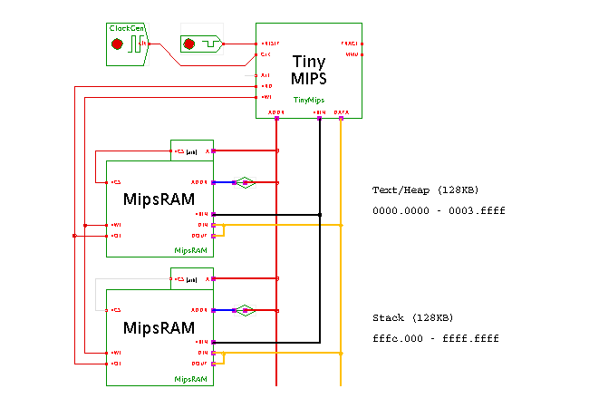
Please check the previous applet for the introduction and description of the TinyMips processor. The hardware structure shown here consists of the processor, some glue logic, and two MipsRAM memory components. Two address-decoder components are used to enable one (or none) of the memories via their chip-select inputs, depending on the address generated by the processor. The first (upper) RAM is enabled in the address-range of 0000.0000 to 0003.ffff. It is used to store the program code and the static and heap regions of the data generated during program execution. The second (lower) RAM is enabled in the address-range of fffc.0000 to ffff.ffff and used to store the program stack. The initialization code used in this applet does not explicitly initialize the stack pointer register, which remains at its reset value of 0000.0000. As the stack in gcc-compiled code grows down, the first procedure calls wraps around from zero to the highest possible word address (ffff.fffc). You should open both memory editors (and optionally the TinyMips processor register editor) to watch the program execution.
Once the simulation has started, you should immediately open the memory editor window, so that you can watch the program execution. As is typical for embedded systems, our hardware structure lacks any easy means for debugging output. Therefore, we write some fancy (or rather silly) values into the main memory to indicate the different phases of the program. Also, the sum_recursive function stores it current intermediate value into memory locations starting at byte address 0x00000400 (in the upper MipsRAM component).
Note that the program does not adjust the stack pointer. Instead, the compiler defaults are used; the stack is placed at the bottom of the address space, and groes down. Please scroll down in the memory editor to watch the stack accesses during execution of the program. Note that the compiler reserves enough space for the temporary variables required for the summation function in each stack frame.
Usage
Wait until the applet is loaded. You can now open the memory-editor (via popup > edit) windows of both RAM components. The memory editor highlights the last read operation in green color, and the last write operation in cyan color, which allows you to easily watch the program execution. If you want to change the simulation speed, just select 'edit' on the clock-generator component, then edit the value of the clock-generator 'period' property, and select 'apply' (and 'ok' to close the clock-generator config dialog).
Similarly, open the TinyMips user-interface window (via popup > edit) to watch the current register values.
The binary program running on the processor was compiled and linked with the GNU gcc (2.7.2.3) and binutils cross-compiler toolchain on a Linux x86 host, with the final ELF loading and relocation done via the Hades Elf2rom tool. See:
/* stack.c - check stack depth on Hades Mips */


#define ADDR  0x00000400


int sum_recursive( int value ) {
  int* ptr;

  ptr = (int*) ADDR;

  if (value == 0) {
    *ptr = 0;
    return 0;
  }
  else {
    *(ptr+value) = value;
    return value + sum_recursive( value-1 );
  }
}


int main( void ) {
  int i;
  int * ptr;

  ptr = (int*) ADDR;
  *(ptr-4) = 0xcafe0001;
  i = sum_recursive( 15 );

  *(ptr-8) = 0xcafe0002;
  i = sum_recursive( 37 );

  *(ptr-12) = 0xcafe0003;
  i = sum_recursive( 876 );

  *(ptr-16) = 0xcafe0004;
  i = sum_recursive( 4097 );

  *(ptr-20) = 0xcafe0004;
  for( i=0; ; i++ ) {
    *ptr = i;
  }
}
Run the applet | Run the editor (via Webstart)