
 |  |
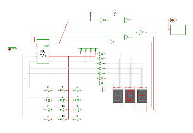
 DescriptionThe MIDI footswitch controller yet again,
but running the internally clocked FastPic16C84 microcontroller model
and using our special multiplexed seven-segment display
simulation models.
These display simulation models internally keep statistics of how
long each display segment was activated during a sample period.
All segments that were active for more that a specified threshold period
are then shown active in the editor canvas.
The timing parameters for the displays can be set via the property sheet.
As a result of using the multiplexed display, you should be able to really 'play' with the circuit and watch the visual feedback from the display.
Note that the displays will indicate a short-circuit condition on the microcontroller bus as long as switches are pressed. In the original circuit, series resistors are used between the three switch output lines and the corresponding port B lines to avoid this problem. Unfortunately, it is impossible to model the series resistors using the std_logic_1164 logic system. Either a full analog circuit simulator or an even more complex digital logic system than std_logic_1164 would be required to correctly model such situations.
For a description of the circuit and program, check the previous applet page or click here. Run the applet | Run the editor (via Webstart)