

| |
 Description
This applet demonstrates the transmitter part of a serial communications
interface.
The circuit converts incoming 8-bit ASCII (or rather ISO-8859-1) data
into a serial RS-232 protocol data stream at 1200 baud.
For the corresonding serial-to-parallel converter, see the
receiver demonstration applet.
Description
This applet demonstrates the transmitter part of a serial communications
interface.
The circuit converts incoming 8-bit ASCII (or rather ISO-8859-1) data
into a serial RS-232 protocol data stream at 1200 baud.
For the corresonding serial-to-parallel converter, see the
receiver demonstration applet.
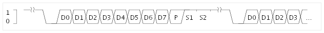
The RS-232 protocol for serial data communication is rather simple. For a thorough explanation, see the Wikipedia article. To indicate the beginning of a data transmission, the transmitter first drives the signal line to the low (active) state for one period of the transmitter clock. This is called the start bit. During the next periods of the transmitter clock, the selected number of data bits (usually five to eight) are transmitted starting with the least significant bit. Optionally, a parity bit is inserted after the most significant data bit. Finally, the signal line is kept high (passive) for at least one transmitter clock period; this is called the stop-bit. Often, two-stop bits are used. The example figure below shows the transmission with one startbit, eight databits, parity bit, and two stopbits. Note that the actual circuit used in this applet does not generate the parity bit:
The circuit shown here consists of a 'parallel terminal' circuit that generates the 8-bit parallel input data, the actual parallel-to-serial-converter, and a standard serial RS-232 terminal. The counters are just for visualization, because the repainting will be much to slow to follow the serial communication data, despite the comparatively slow baud-rate of 1200 baud.
When the applet is first loaded, it will open two extra windows, one for each of the terminals. Whenever you type into the 'parallel terminal' window, the terminal will output the corresponding ASCII data on its eight data output ports and generate one short 'strobe' pulse.
The strobe pulse in turn triggers the parallel-to-serial conversion sequence. The output from the converter is then fed into the second 'serial terminal', which receives and decodes the RS232 protocol data and displays the corresponding data. The net result is that the serial terminal displays the data that you type into the parallel terminal.
To show or hide the terminal windows, simply click on the terminal symbols in the schematics editor. Unfortunately, several browsers still have bugs with the handling of keyboard focus for Java applets. If necessary, bring the 'parallel terminal' window into the front and try a mouse-click into the window to guarantee that the window has the keyboard focus, before you start typing into the window. For a screenshot of the transmitter demonstration with both terminal windows open, click here
The following image shows example waveform while transmitting the input data (D0..D7) = (10100110):
Integrated circuits that combine both the transmitter and the receiver components are called UARTs (for universal asynchronous receiver and transmitter). These chips usually support a variety of configuration options for the serial communication including additional handshake signals and high speed transmission at baud-rates up to 115 kbps. Due to the comparatively slow interrupt handling on typical PCs, additional chip internal buffers are often used to avoid data loss due to overrun at high baud-rates. Check the 8251 USART applet for a demonstration of the Intel 8251 chip.
Run the applet | Run the editor (via Webstart)