
 |  |
 Description
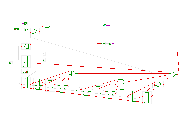
The controller state-machine for the parallel-to-serial converter.
While the similar controller shown in the
RS-232 applet
is based on the Hades state-machine editor,
this applet shows a complete gate-level implementation.
The transmitter circuit is controlled by a single strobe input signal. A rising-edge on that signal latches the input data into the data input-buffer register and is expected to trigger the transmission. To guarantee the correct bit timing for the RS-232 output signal, the output shift-register and all state-flipflops in this controller are clocked with the baud-clock input signal. As the duration of the strobe signal pulse may be shorter than the baud-clock period, it is not sufficient to use the strobe signal as a direct input to the controller state-machine. Instead, a separate SR-flipflop is required to ensure that the strobe pulse is recognized by the controller.
The state-machine itself consists of a set of D-type flipflops connected into a shift-register. In the idle state, all flipflops store the value zero, and the busy output is de-asserted. Also, the SR-flipflop is reset. The cascade of AND gates is driven by the negative output of all flipflops, so that all AND gates inputs except for the SR-flipflop are active. Even a single short pulse on the strobe signal will then set the SR-flipflop, which in turn activates the AND gate cascade output. On the next rising-edge of the baud-clock signal, the first flipflop will be set. This activates the Load shifter output, so that the shift-register will load the current contents of the data-buffer register on the next rising-edge of the clock signal. It also de-activates the cascade of AND-gates, so that the input value of the first flipflop is zero again. As a result, a single one-bit propagates through the chain of shift-register flipflops during the next few clock-cycles. At the same time, the transmission shift-register outputs the start-bit, data-bits D0, D1, D2, D3, D4, D5, D6, D7, the parity-bit, and stop-bit. As soon as the one-bit reaches the last flipflop, the SR-flipflop is reset, and the transmission sequence stops.
The circuit also includes a second overrun output, which is meant to indicate that a new strobe input pulse arrived while a transmission is active (busy asserted). This is an error, because the second strobe pulse and corresponding data would be lost.
Run the applet | Run the editor (via Webstart)