
 |  |
 DescriptionA stack controller
realized with the Hades interactive state-machine editor.
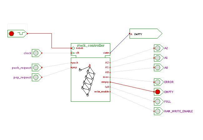
The state machine used in the applet is designed to manage a stack memory (first in last out) realized with an external static random-access memory (RAM) As such, the stack controller has to generate both the current address and the write-enable signal for the RAM. We assume that the RAM has separate read and write ports, so that no extra read-control or output-enable signals are necessary. This leaves us with the address outputs (here A2, A1, A0) and the write-enable output (assumed to be active high for clarity). A few extra active-high status outputs are provided to indicate the current condition of the stack: empty, full, underflow, and overflow.
The stack is controlled by two active-high input signals, called pop and push. When pop is high during a rising edge of the clock signal, the stack performs a pop operation. That is, the current memory address is decremented (and the corresponding memory data appears at the memory read port shortly afterwards). When pop is low but push is high, the memory address is incremented and the current input data (from the external input) is written into the memory. Otherwise (both push and pop low), the stack controller keeps the memory address and does nothing.
As both the pop and the push operations are performed in a single cycle, we two need separate states to distinguish between read and write operations. If an idle cycle occurs after a write cycle, the state changes from the write state to the corresponding read state with the same memory address. (In real circuits, single-cycle operation is not too realistic because the external memory might be too slow or otherwise require a more complex multi-cycle command sequence).
An attempt to pop data from an empty stack results in a transition to the UNDERFLOW state. You will need to reset the state machine after an underflow occured. Similarly, an attempt to push new data into a full stack results in a transition to the OVERFLOW state. Again, a reset is required to restore the stack state machine.
For a demonstration of the complete circuit including controller and memory, visit single-cycle clocked stack demonstration applet in the RTLIB chapter. Instead of a single rather large and complex state machine, two flipflops and a separate address counter are used in that demo.
Run the applet | Run the editor (via Webstart)