
 |  |
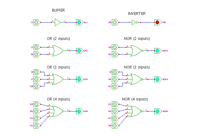
 DescriptionA demonstration of varous OR logic gates.
Click the input switches to toggle the corresponding input value
between 0 and 1, and watch the resulting behaviour.
You can also use shift+click to toggle the input value between
the states 0, 1, Z (tri-state, not driven) and X (undefined).
Again, the default input values of the switches are chosen
so that the first mouse-click already changes the output value
of the corresponding gate.
The left column includes the non-inverting gates ('positive logic'), namely the one-input buffer and the OR gates with two, three, and four inputs. The right column shows the inverting gates: inverter, NOR gate, and NOR gates with two, three, and four inputs. As explained in the previous applet (AND gates), most current technologies are actually based on the inverting gates. In CMOS technology, the four non-inverting gates are realized by the inverting gate followed by an inverter.
Naturally, it is easy to define logic gates with more than four inputs, but these are rarely used in practice due to technological restrictions. While bipolar technology might allow gates with perhaps up to about six inputs, most MOS techology libraries only include OR and NOR gates with up to four inputs (see the AND gate page for a detailed explanation).
To explore the circuit, just click the corresponding switches, or type the following keys:
Run the applet | Run the editor (via Webstart)