
 |  |
 Description
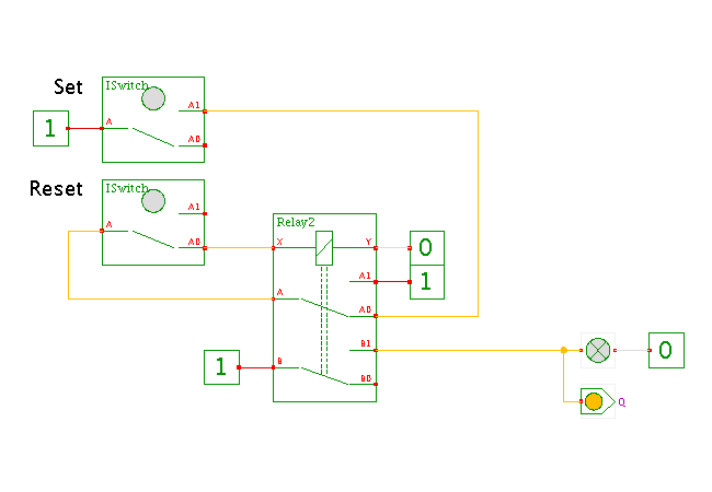
This applet demonstrates the basic relay set-reset flipflop.
Click the input switches to control the circuit and observe
the resulting behavior.
(The bindkeys 's' and 'r' are not implemented yet.)
In the circuit shown here, the relay coil and the 'reset' switch are connected in series. Therefore, whenever you press the 'reset' switch, the relay coil is disconnected and the relay will be deactivated.
When the 'reset' switch is in its default 'off' position, the 'X' connection of the relay coil is connected to the first relay switch. As soon as you press the 'set' switch, the relay coil will be driven via the upper A-A0 contact of the relay switch, and the relay activates. This in turn activates the A-A1 contact of the relay switch, and the relay will stay activated when you release the 'set' switch.
The resulting truth table is as follows:
  SET  RESET  |  Q    Q*
--------------+-------------------
    0      0  |  *    Q   (store)
    0      1  |  *    0   (reset)
    1      0  |  *    1   (set)
    1      1  |  *    0   (reset)
While the SR flipflop shown here only uses a single relay, it requires the use of an normally-closed-type switch (interruptor) to reset the flipflop. If such switch is not available, a second relay can be used, as shown in the following applet.
Run the applet | Run the editor (via Webstart)