
Applets
contents
visual index
 introduction
 std_logic_1164
 gatelevel circuits
 delay models
 gate vs. wir...
 gate delay d...
 ring oscillator
 hazards
 NAND-chain
 D-flipflop h...
 clock-doubler
 2-phase cloc...
 flipflops
 adders and arithm...
 counters
 LFSR and selftest
 memories
 programmable logic
 state-machine editor
 misc. demos
 I/O and displays
 DCF-77 clock
 relays (switch-le...
 CMOS circuits (sw...
 RTLIB logic
 RTLIB registers
 Prima processor
 D*CORE
 MicroJava
 Pic16 cosimulation
 Mips R3000 cosimu...
 Intel MCS4 (i4004)
 image processing ...
 [Sch04] Codeumsetzer
 [Sch04] Addierer
 [Sch04] Flipflops
 [Sch04] Schaltwerke
 [Sch04] RALU, Min...
 [Fer05] State-Mac...
 [Fer05] PIC16F84/...
 [Fer05] Miscellan...
 [Fer05] Femtojava
 FreeTTS
 Ring oscillators are often used as prototype circuits
to test new semiconductor processes, because they are so simple
and therefore very easy to design.
They also allow to run the gates of the new process at optimal speed,
which is ideal to optimize the design parameters and layout rules
for the new process.
In such cases, usually one or a few of the gate outputs are
connected to buffers, which are then routed to output pads
of the integrated circuits and to external equipment like counters
and oscilloscopes.
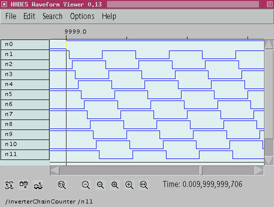
While the single gates operate at very high frequencies
(e.g. a few picoseconds of delay), the resulting ring oscillator
output frequency is essentially divided by the number of gates in the
circuit and therefore accessible to external equipment.