

| |
 Description
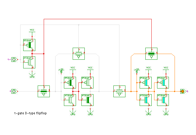
A switch-level demonstration of the CMOS transmission-gate
rising-edge triggered D-type fliplop,
shown as a complete transistor-level schematics.
See the next applet for a simplified way to draw this circuit.
Description
A switch-level demonstration of the CMOS transmission-gate
rising-edge triggered D-type fliplop,
shown as a complete transistor-level schematics.
See the next applet for a simplified way to draw this circuit.
Click the input switches or type the 'c' and 'd' bindkeys to control the clock and data inputs.
The edge-triggered flipflop is built from two D-type level-triggered latches (see the previous applets). Both latches are enabled with opposite polarity of the clock signal: The second (or slave) latch is controlled by the clock signal, while the first (or master) latch is enabled by the negated clock.
As a result of this wiring of the clock signal, the first latch is transparent while the clock signal is low, and the current value of the D input is propagate to the input of the second latch. However, the input t-gate of the slave latch is non-conducting. Therefore, the flipflop stores its current value (regenerated via the feedback loop of the slave latch).
On the rising edge of the input clock, several things happen. First, the input t-gate of the master latch becomes non-conducting, while the feedback t-gate of the master latch becomes conducting. That is, the master latch stores its current value - the value it had immediately before the rising-edge of the clock signal. At the same time, the slave latch becomes transparent (its input t-gate is now conducting) and therefore outputs the value stored in the master latch. The new output value arrives at the Q output about three transistor delays (slave input t-gate, two invertage stages) after the rising edge of the clock signal.
When the clock signal turns low again, the input t-gate of the slave latch becomes non-conducting, while the feedback t-gate becomes conducting. That is, the slave latch keeps storing its current value, namely the value loaded during the preceding rising-edge of the clock signal into the master latch. At the same time, the master latch becomes transparent again and the D input value is propagated through the master latch onto the (now non-conducting) input t-gate of the slave latch.
  CLK  D  |  Q+
 ---------+------
    0  *  |  Q  (storing old value)
    1  *  |  Q  (storing old value)
    ^  *  |  D  (loading new value on rising-edge of clock)
Run the applet | Run the editor (via Webstart)